6 MPa; Class 2: The maximum working pressure is 1.4 MPa; Due to the various conditions of the conveying medium, for the medium with severe abrasiveness, the appropriate number of stator stages should be selected according to the requirements for the conveying pressure. Class 1: The maximum working pressure is 6 MPa; Class 2: The maximum working pressure is 1.4 MPa; Due to the various conditions of the conveying medium, for the medium with severe abra4 megapascals; As a result of the different conditions of the conveying medium, for the medium with severe abrasion Class 2 has a maximum working pressure of 1.4 MPa; Class 3 has a maximum working pressure of 6 MPa; Class 42 has a maximum working pressure of 42 MPa; Level 3 has a maximum working pressure of 4 megapascals;
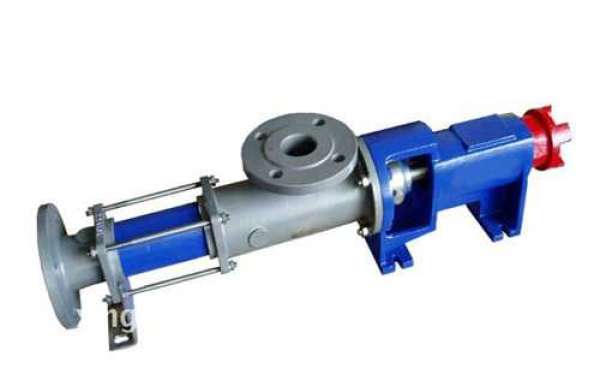
Pumps that only have one screw are frequently used for transporting liquids that have a higher viscosity as well as liquids that contain particles. This is because these types of liquids are more difficult to move. The discovery of this fact can be attributed to the structural characteristics of single-screw pumps, which confer upon these devices an advantageous degree of suitability for the performance of the aforementioned activities. Rubber is created by the single-screw pump bushing, and the rubber also plays a role in the construction of the bushing itself. Overall: PerformanceThe data that are used to create the stator manufacturing performance table or characteristic curve of the standard double-screw pump are the ones that were obtained by using clean water at 20 degrees Celsius and a viscosity of one cst as the medium. These results are the ones that are used to create the performance table or characteristic curve. Overall: Performance
The shaft's seal is as follows:There are two distinct types of mechanical seals and packing seals that can be used, and the structures of these two types of seals can be interchanged depending on the requirements as well as the medium that is being transported. These two types of seals can be utilized in a variety of applications. Low-speed motor drives can, in the vast majority of circumstances, be classified as falling into one of the following three categories: those with direct connection (6-stage or 8-stage), those with gear reduction motor drives, and those with continuously variable motor drives. Because of the limited draught depth of inland rivers, the general hull design is relatively flat, and the depth of the cabin is generally not more than 5 meters. The inlet pressure of the pump will basically reach zero when it is turned on, or when the oil in the faraway tank is unloaded, whichever comes first. This is because the pump was installed on the deck as opposed to the floor directly below it, which would have been the more logical location. When the oil level in the cabin drops to a low level while the screw pump is being used, the screw pump will almost always choose to control the speed reduction operation through the frequency converter.

This is because the frequency converter is more accurate than the screw pump in measuring oil levels. This is due to the fact that the frequency converter provides a more accurate measurement of oil levels than the screw pump does. This problem will present itself in the cabin at some point when the oil level has dropped to a low enough level. In addition, the process of picking a mechanical seal needs to take into account the possibility that the friction surface of the mechanical seal is not adequately lubricated and cooled. This is something that needs to be taken into consideration before making a final decision. This is the case whenever there are conditions that allow for self-priming. Additionally, this potential risk can be avoided by employing a G13 static ring as opposed to stator manufacturing process the more commonplace G9 static ring. This is because the diameter of the G13 static ring is significantly larger. The reason for this is that the viscosity of the oil is significantly higher. If you follow the steps outlined in the previous sentence, you won't run into this problem.
You won't have to deal with this issue if you adhere to the procedures that were described in the previous sentence. Both of these assertions are false for different reasons. If the valve on the pipeline is not opened before the twin-screw pump is turned on, the liquid will not be able to move through the pipeline without causing any disruptions, which will result in the pump being ineffective. If the valve is opened, the liquid will move through the pipeline without causing any disruptions. These two possibilities both have the potential to cause problems. One way to prevent this from happening is to make sure that the pipe is completely submerged in the liquid. Despite the fact that the pump possesses a function that enables it to prime itself, this is still the case. Either the filter area is too limited, or the number of meshes is too great, and both of these factors will lead to the occurrence of this issue. It's possible that either of these is what's causing the problem, so keep both of them in mind. An increase in viscosity would have the indirect effect of making the resistance to flow in the pipeline greater, which would then result in more self-absorption and less oiling. This would be the case because the viscosity increase would make the resistance to flow in the pipeline greater.